Outrageous Tips About What Are The 3 Basic Logic Gates

Unlocking the Secrets of Digital Circuits
1. The Building Blocks of Modern Technology
Ever wonder what makes your phone, computer, or even your toaster oven tick? (Okay, maybe not your toaster oven, but some modern ones are surprisingly sophisticated!) At the heart of all these digital marvels are tiny little switches that control the flow of electricity, based on logic. And that logic is implemented using what we call logic gates. Sounds complicated, right? Don't worry, we'll break it down. Think of them as the ABCs of the digital world. The foundation upon which everything else is built. We're going to explore the fundamental concepts behind the three basic logic gates — AND, OR, and NOT.
Imagine you're trying to decide whether to go to the movies. You might think, "I'll go AND my friend goes too." That's an AND gate in action! Or maybe, "I'll go OR I'll watch a movie at home." That's an OR gate! And if you decide, "I will NOT go if it's raining," you're using a NOT gate. These simple decisions, translated into electrical signals, form the basis of all digital computation. This is how a simple light switch can control a massive network or allow a single computer to power a global network.
These aren't just abstract concepts; they're physically embodied in tiny electronic components called transistors, cleverly arranged to perform these logical operations. Transistors work like tiny switches, controlling the flow of electricity based on input signals. The beauty of it all lies in the simplicity: combining these gates in various ways allows us to create incredibly complex circuits that can perform calculations, store data, and control devices.
So, buckle up as we dive into the fascinating world of logic gates, demystifying their functions and revealing their crucial role in shaping the technology we use every day. You might even impress your friends at the next tech gathering with your newfound knowledge!

Understanding the AND Gate
2. Both Conditions Must Be True
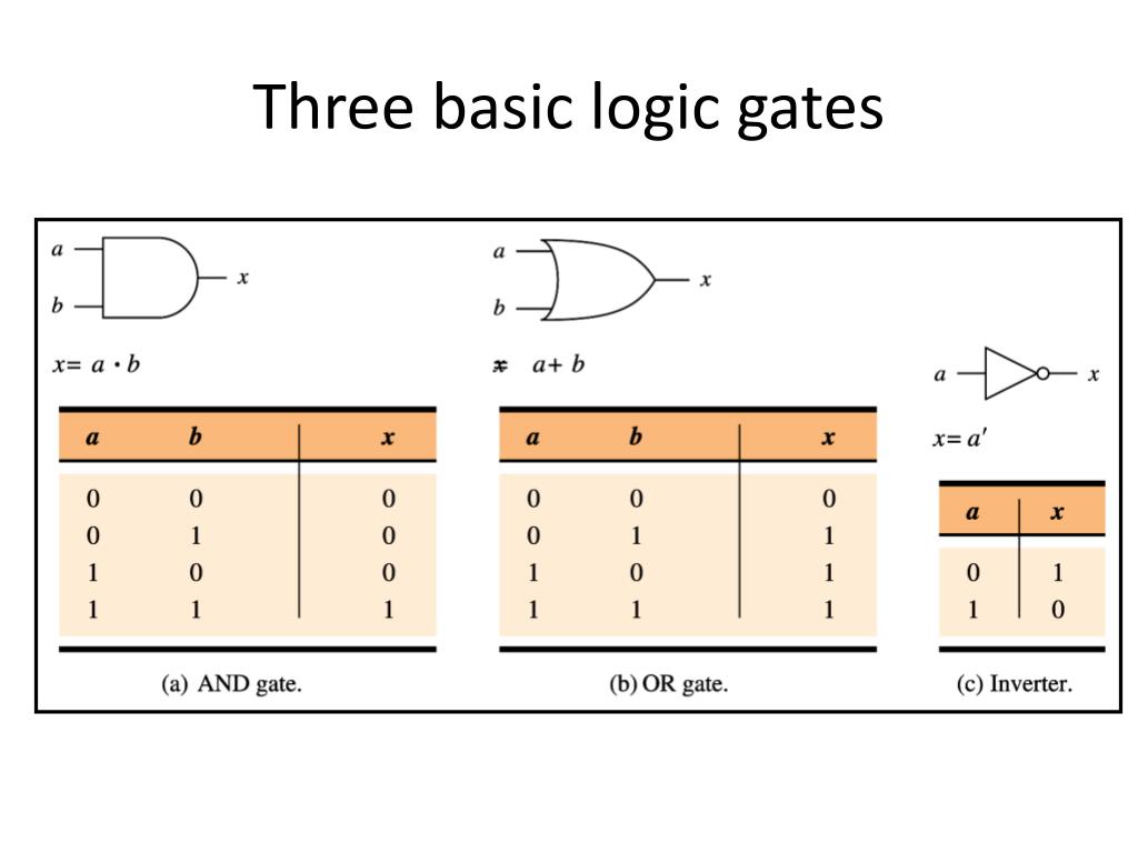
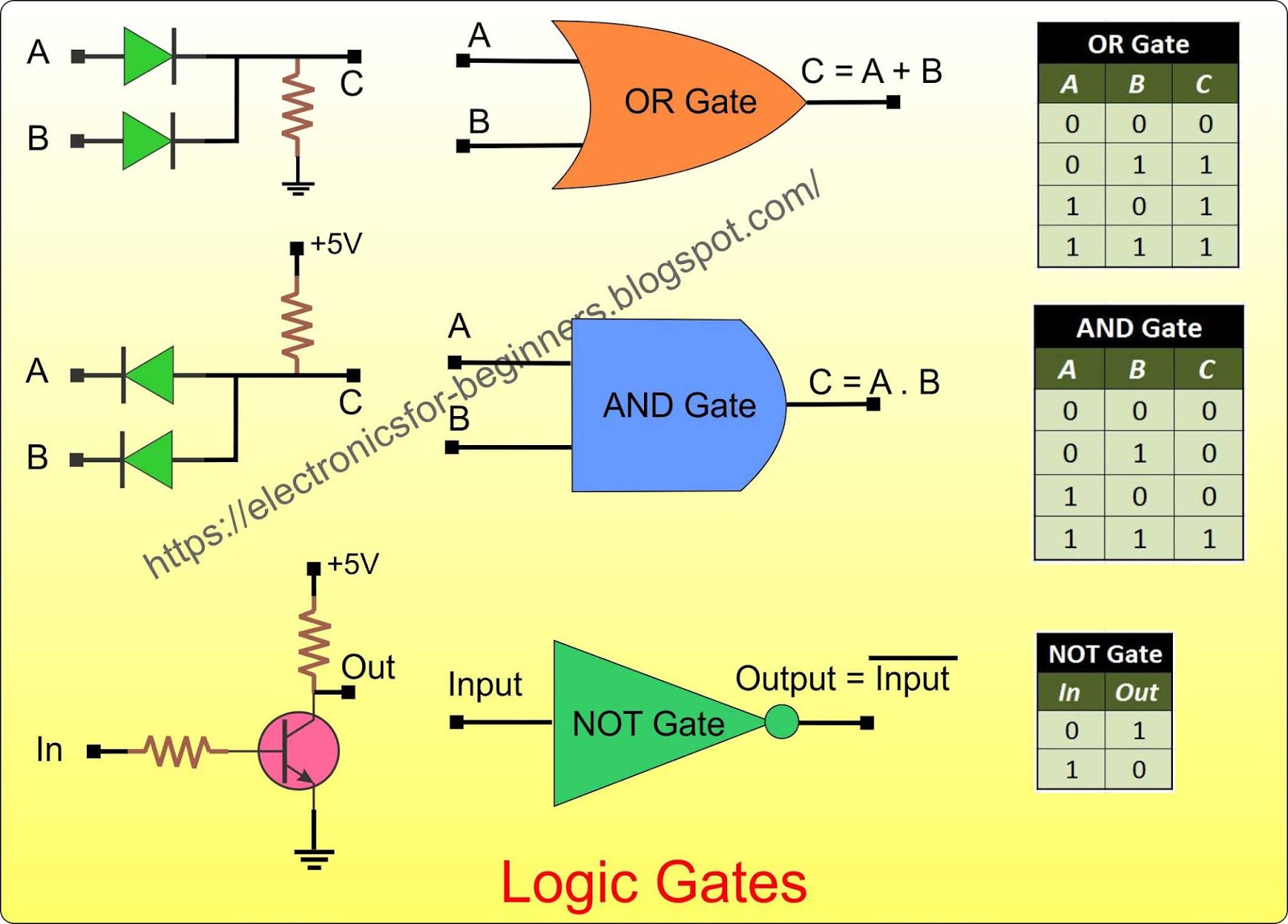
Let's kick things off with the AND gate. This gate is pretty straightforward. It only outputs a "true" (or 1) signal if ALL of its inputs are "true" (or 1). Think of it like a demanding boss who requires everything to be just right before giving the green light. If even one input is "false" (or 0), the output will be "false" (or 0).
To visualize this, imagine a scenario where you need two keys to unlock a treasure chest. One key is held by you (input A), and the other is held by your friend (input B). Only when BOTH you AND your friend insert their keys will the chest open (output 1). If either of you is missing, the chest remains locked (output 0). This illustrates the core principle of the AND gate: both inputs must be true for the output to be true.
In the digital realm, the AND gate is used for various purposes, such as enabling a certain function only when specific conditions are met. For instance, a seatbelt alarm in a car might be connected to an AND gate. One input would be whether the car is in motion, and the other would be whether the seatbelt is fastened. Only if BOTH conditions are true (car moving AND seatbelt unfastened) will the alarm sound. Annoying, but effective!
AND gates can have more than two inputs. The basic principle still applies: the output will only be "true" if all inputs are "true." So, if you had a three-input AND gate, all three inputs would need to be 1 for the output to be 1. Otherwise, the output is 0. This makes the AND gate a valuable tool for ensuring that multiple conditions are satisfied before triggering a specific action in a digital circuit.

Basics Of Logic Gates At Tonya Barnes Blog
Exploring the OR Gate
3. One Condition is Enough
Next up is the OR gate, a much more lenient logic gate compared to the AND gate. The OR gate only requires one of its inputs to be "true" (or 1) for the output to be "true" (or 1). Think of it like this: you're happy if you get either pizza OR ice cream. You don't need both; one is enough to satisfy you!
Imagine a light bulb connected to two switches. If you flip either switch, the light turns on. It doesn't matter which switch you use; as long as at least one switch is on, the light shines brightly. This illustrates the OR gate perfectly: If either input A or input B is 1, the output is 1.
OR gates are frequently used in situations where any of several conditions can trigger a particular response. For example, in a security system, an alarm might be connected to an OR gate with inputs from various sensors — a door sensor, a window sensor, and a motion detector. If any of these sensors are triggered, the alarm will sound, alerting you to a potential intrusion. One sensor going off will activate the alarm.
Similar to AND gates, OR gates can also have more than two inputs. With a multi-input OR gate, the output will be "true" if at least one of the inputs is "true." Only if all inputs are "false" will the output be "false." This makes the OR gate incredibly versatile for situations where multiple possibilities need to be considered.
![[DIAGRAM] Logic Diagram Gates [DIAGRAM] Logic Diagram Gates](https://d2vlcm61l7u1fs.cloudfront.net/media/c38/c387ee42-ab5d-49a3-95ae-72d8ec8889ab/phpOH9onu.png)
[DIAGRAM] Logic Diagram Gates
The NOT Gate
4. Flipping the Script
Last but not least, we have the NOT gate. This gate is a bit of a rebel; it simply inverts its input. If the input is "true" (or 1), the output is "false" (or 0), and vice versa. Think of it as a translator that always says the opposite of what it hears. It's the simplest of the 3 basic logic gates.
Imagine a sign that says, "Do NOT enter." If you see the sign (input 1), the correct action is to NOT enter (output 0). Conversely, if you don't see the sign (input 0), you are free to enter (output 1). This represents the behavior of the NOT gate: it always flips the input value.
NOT gates are used in a wide variety of applications, often in conjunction with AND and OR gates to create more complex logic functions. For example, you might use a NOT gate to invert a signal before it's fed into an AND gate, effectively creating a "NAND" (NOT AND) gate. NAND gates are actually very common and can be used to build any other type of logic gate.
Unlike AND and OR gates, the NOT gate only has one input. Its sole purpose is to negate the input signal. It's a small but essential piece of the digital puzzle, allowing us to create more sophisticated and flexible circuits. Without the NOT gate, our ability to manipulate and control digital signals would be severely limited.

Compuertas Logicas Basicas Hardware Description Language Logic Gate Images
Putting It All Together
5. Combining the Basic Logic Gates
Now that you're familiar with the three basic logic gates, you might be wondering how they're used in real-world applications. The answer lies in combining them to create more complex circuits that can perform a variety of tasks. By strategically connecting AND, OR, and NOT gates, engineers can design circuits that add numbers, control machines, and even run entire operating systems.
Think back to our earlier example of the car seatbelt alarm. While we simplified it to a single AND gate, a more realistic implementation would involve a combination of gates. For instance, there might be sensors in multiple seats, and the alarm should only sound if all occupied seats have unfastened seatbelts. This would require combining AND gates with OR gates to check the status of each seat and trigger the alarm appropriately. The use of 3 basic logic gates is very important
The possibilities are truly endless. By carefully designing the connections between gates, engineers can create circuits that perform incredibly complex functions. These circuits are the foundation of everything from your smartphone to the International Space Station. They are a critical part of all modern electronics.
So, the next time you use a computer or any other electronic device, remember the humble logic gate. These tiny building blocks are the unsung heroes of the digital age, quietly and efficiently powering the technology that shapes our world. Understanding them is a key to unlocking the secrets of the digital realm, and hopefully, this article has helped you on that journey!

Logic Gate Schematic Maker
Frequently Asked Questions (FAQs)
6. Your Burning Questions Answered
Let's tackle some common questions about the 3 basic logic gates.
Q: What's the difference between an AND gate and an OR gate?
A: The AND gate requires all inputs to be true for the output to be true, while the OR gate only requires one input to be true for the output to be true. Think of it like a group project: with AND, everyone needs to contribute for the project to succeed; with OR, only one person needs to do the work (though that's not ideal!).
Q: Can I build any digital circuit using just AND, OR, and NOT gates?
A: Absolutely! These three gates form a complete set, meaning that any other logic gate or digital circuit can be constructed using just these three. In fact, sometimes you can even get away with using just NAND gates (which are made from AND and NOT gates) to build everything!
Q: Are logic gates just theoretical concepts, or are they real physical components?
A: They are very real! Logic gates are implemented using transistors, which are tiny semiconductor devices that act as switches. These transistors are arranged in specific configurations to perform the logical operations of AND, OR, and NOT gates. You can find these gates packaged as individual chips or integrated into larger integrated circuits (ICs).