Build A Info About Do Servos Use PWM

Apa Itu PWM Dan Fungsinya? Elektrologi
Decoding Servo Control
1. What's the buzz about PWM and Servos?
So, you're diving into the world of robotics or electronics and keep hearing about servos and PWM (Pulse Width Modulation). Are they BFFs? Do they need each other like peanut butter and jelly? The short answer is yes, PWM is the key to controlling these little powerhouses. Think of PWM as the language your microcontroller uses to talk to your servo, telling it exactly where to go.
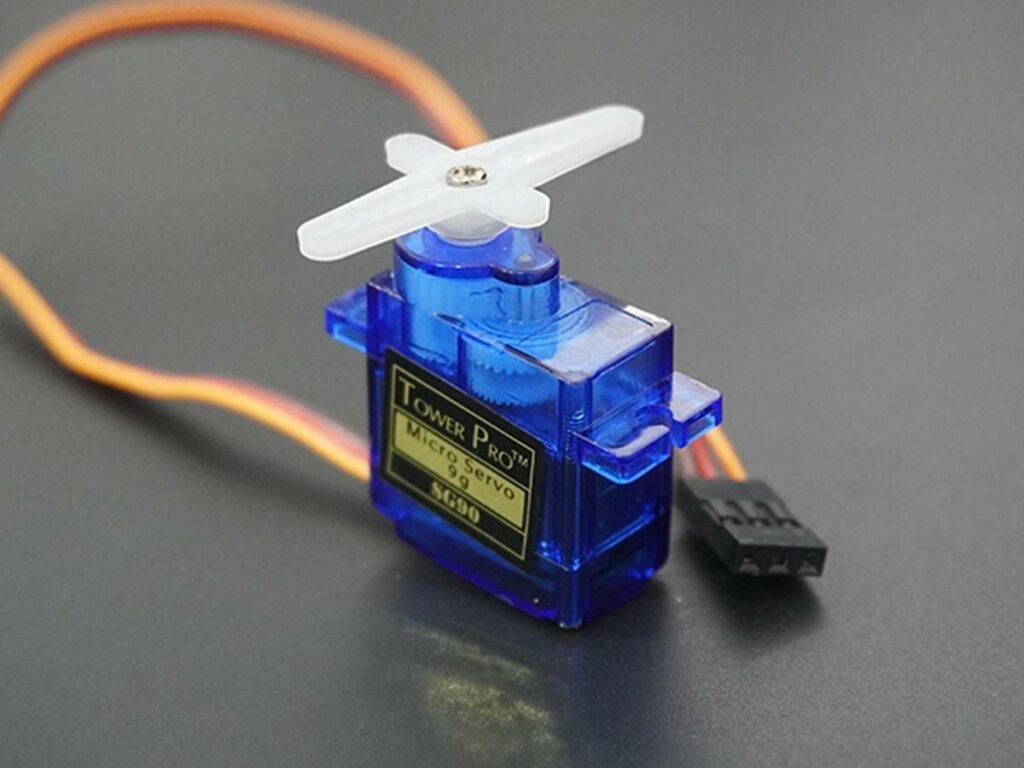
Servos are basically tiny motors with built-in control circuits that can rotate to a specific position. They're found everywhere from RC cars and airplanes to industrial robots. What makes them special is their ability to hold their position, even against some resistance. They're not just spinning wildly; they're precisely controlled.
But how does this precise control actually happen? That's where PWM comes in. PWM is a clever technique that uses a series of pulses to simulate an analog signal. By varying the width of these pulses, we can control the servo's angle with great accuracy. It's kind of like Morse code, but instead of dots and dashes representing letters, you have short and long pulses representing angular positions.
Without PWM, controlling a servo would be like trying to steer a car with your eyes closed. You might get lucky and eventually reach your destination, but the journey will be bumpy and unpredictable. PWM provides the precision and stability needed for accurate servo control.

Transmitter Module Pwm Servo
Peeking Under the Hood
2. The Secret Sauce of Pulse Width Modulation
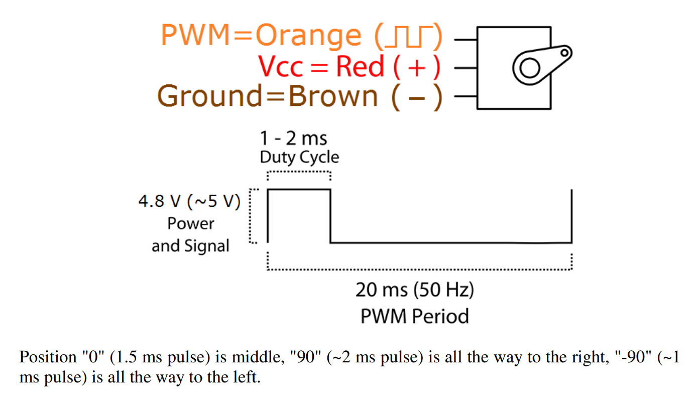
Alright, let's get a little more specific. PWM works by sending a repeating signal to the servo. This signal is characterized by two things: its period (the time it takes for one complete cycle) and its duty cycle (the percentage of time the signal is high during that period). It's like a light switch that flickers on and off rapidly. The amount of time the light is on versus off determines the brightness.
For servos, the duty cycle corresponds to the desired angle. A typical servo expects a pulse width between 1 millisecond (ms) and 2 ms, repeated every 20 ms. A 1 ms pulse might tell the servo to go to 0 degrees, a 1.5 ms pulse might command it to move to 90 degrees, and a 2 ms pulse could signal it to rotate to 180 degrees. These values can vary slightly depending on the specific servo model, so always check the datasheet.
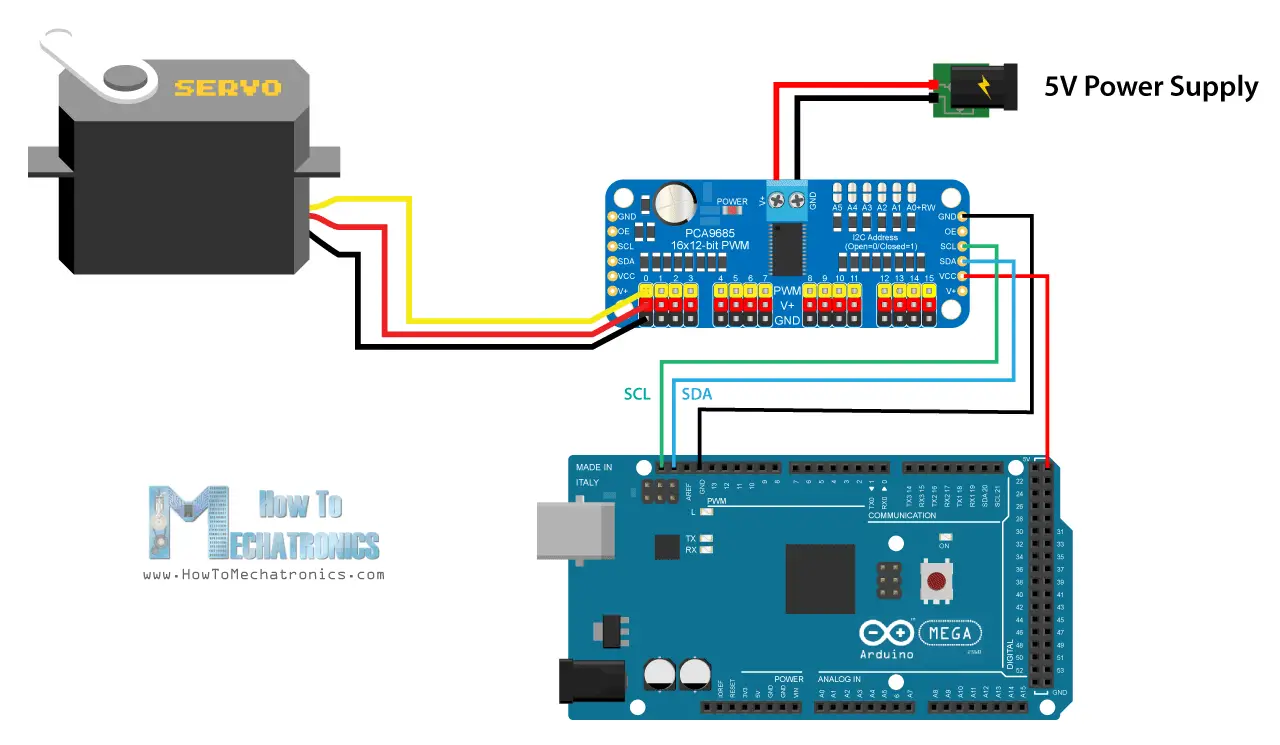
Your microcontroller (like an Arduino) generates this PWM signal. You tell the Arduino what angle you want, and it translates that into the correct pulse width. The servo's internal circuitry then compares the incoming pulse width to its own internal potentiometer (a variable resistor). If there's a difference, the motor spins until the potentiometer matches the pulse width, effectively reaching the desired angle.
Think of it as a miniature feedback loop. The microcontroller sends a command, the servo executes it, and the servo reports back its position via the potentiometer. This constant feedback ensures accurate and reliable positioning. So, next time you see a robot arm smoothly moving into position, remember that it's all thanks to the magic of PWM!

Beyond the Basics
3. Not all Servos are Created Equal (Especially with PWM!)
While the fundamental principle of using PWM to control servos remains the same, there are nuances depending on the type of servo. Standard servos, like the ones we've been discussing, are position-controlled. They move to a specific angle and hold it there. However, there are also continuous rotation servos, which are essentially geared DC motors that can rotate continuously in either direction.
With continuous rotation servos, the PWM signal doesn't control the angle but rather the speed and direction of rotation. A pulse width of 1.5 ms might stop the motor, while a slightly shorter pulse width could cause it to rotate clockwise, and a slightly longer pulse width could make it rotate counterclockwise. The further away from 1.5 ms the pulse width is, the faster the motor spins.
Then there are digital servos, which are more sophisticated than analog servos. They often have higher resolution and faster response times. Digital servos use a microcontroller internally to process the PWM signal and control the motor. This allows for more precise control and customization. They can also be programmed with different parameters, such as speed limits and acceleration profiles.
Choosing the right servo and understanding its PWM requirements is crucial for any project. A standard servo is perfect for applications requiring precise angular positioning, while a continuous rotation servo is ideal for driving wheels or other rotating mechanisms. Digital servos offer the highest performance but come at a higher price.

Best 12 How To Make A Simple Servo Motor Tester Circuit? Artofit
Troubleshooting Servo Woes
4. When PWM Doesn't Play Nice
Even with a solid understanding of PWM and servos, things can sometimes go wrong. Your servo might jitter, not move at all, or behave erratically. Often, these issues can be traced back to problems with the PWM signal or the power supply.
One common problem is a noisy or unstable PWM signal. This can be caused by poor wiring, interference from other devices, or an inadequate power supply. Make sure your wires are properly connected and shielded, and that your power supply can provide enough current for the servo. Using a capacitor across the servo's power leads can also help to smooth out voltage fluctuations.
Another issue can be incorrect PWM settings. Double-check that you're using the correct pulse width range and frequency for your specific servo model. Also, make sure your microcontroller is generating a clean and consistent PWM signal. If you're using a library, review its documentation and examples carefully.
Sometimes, the problem might not be with the PWM signal itself but with the servo's internal circuitry. If you've tried everything else and your servo is still misbehaving, it might be defective. Try testing it with a different microcontroller or power supply to rule out other potential issues. And remember, even the best servos can eventually wear out, especially if they're subjected to heavy loads or frequent use.

Cómo Funciona El Servomotor Y Controlar Los Servos Usando Arduino
Servo Success Stories
5. Examples of PWM in action
Now that we've covered the technical aspects of PWM and servo control, let's look at some real-world examples of how this technology is used. From hobby projects to industrial applications, PWM-controlled servos are essential components in countless systems.
In robotics, servos are used for everything from controlling the joints of a robot arm to steering a mobile robot. The precise control offered by PWM allows robots to perform complex tasks with accuracy and repeatability. Imagine a robot assembling intricate electronic components or navigating a crowded warehouse — all thanks to the reliable performance of PWM-controlled servos.
In RC cars and airplanes, servos are used to control the steering, throttle, and flaps. The responsiveness of servos is critical for maintaining control and executing maneuvers. PWM ensures that these control surfaces move smoothly and precisely, allowing pilots and drivers to achieve optimal performance.
Even in everyday life, PWM-controlled servos play a role. Automatic door openers, camera gimbals, and even some home appliances rely on servos for precise motion control. So, next time you see a smooth-operating piece of machinery, remember that PWM is likely working behind the scenes, making it all possible.
